Sunday 4 November 2012

LED Blinking PIC16F877A

void main()
        {
        TRISB = 0 ;     // set PORTB as OUTPUT         for(;;)         // forever
                {
                PORTB = 0xff ;          // turn all LEDs ON
                Delay_ms(500) ;         // wait 500 ms
                PORTB = 0 ;             // turn all LEDs OFF
                Delay_ms(500) ;         // wait 500 ms
                }
        }

Sidharthan G
electricalmiracles.
 

Friday 2 November 2012

Components Of Electrical Substation


A:Primary power lines' side B:Secondary power lines' side
1.Primary power lines 2.Ground wire 3.Overhead lines 4.Transformer for measurement of electric voltage 5.Disconnect switch 6.Circuit breaker 7.Current transformer 8.Lightning arrester 9.Main transformer 10.Control building 11.Security fence 12.Secondary power lines
Sidharthan G
electricalmiracles. File:Electrical substation model (side-view).PNG

LVDT Displacement Transducer

An LVDT Displacement Transducer comprises 3 coils; a primary and two secondaries.

The transfer of current between the primary and the secondaries of the LVDT displacement transducer is controlled by the position of a magnetic core called an armature.


The two transducer secondaries are connected in opposition.

At the centre of the position measurement stroke, the two secondary voltages of the displacement transducer are equal but because they are connected in opposition the resulting output from the sensor is zero.

As the LVDTs armature moves away from centre, the result is an increase in one of the position sensor secondaries and a decrease in the other. This results in an output from the measurement sensor.

With LVDTs, the phase of the output (compared with the excitation phase) enables the electronics to know which half of the coil the armature is in.

The strength of the LVDT sensor's principle is that there is no electrical contact across the transducer position sensing element which for the user of the sensor means clean data, infinite resolution and a very long life.

Our range of signal conditioning electronics for LVDTs handles all of the above so that you get an output of voltage, current or serial data proportional to the measurement position of the displacement transducer.

Sidharthan G
electricalmiracles.

Thursday 1 November 2012

Cell Phone Detector

http://electroschematics.com/wp-content/uploads/2009/01/cellphone-detector.jpg

Earth Fault Indicator circuit

Earth Fault Indicator circuit

This circuit indicates the integrity of wiring connections. It shows all the mains connections – Phase, Neutral and Earth connections – are intact or not. The circuit is too small and can be housed in a three pin plug case.

Earth Fault Indication Circuit Diagram
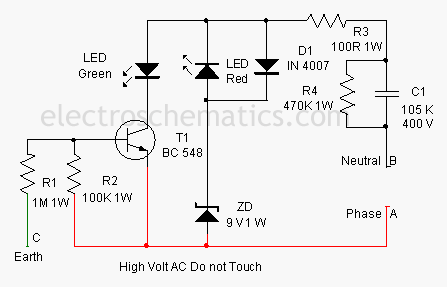


The circuit is directly connected to mains to monitor the status of the connections. Earth connection is a must in domestic wiring to bleed current to the earth if the metal body of a device is accidentally touched with the phase line. This circuit indicates
1. Red and Green LEDs ON Phase, Neutral and Earth OK
2. Red and Green LEDs OFF Phase or Neutral Break / Power failure
3. Red LED ON Phase and Neutral OK
3. Green LED OFF Earth line break
The circuit gets power supply through C1 and R3. AC Capacitor C1 reduces the high volt AC to a safer level through capacitive rectance. Resistor R3 limits the inrush current and R4 gives discharge path for the stored current in C1 when the circuit is unplugged. Zener diode ZD regulates the voltage to a safer level to protect T1 when it is off. Voltage across ZD will be a square wave by the working of C1 and the voltage level depends on the breakdown value of zener (9 volts). When a potential of 230 volt is present between the phase and neutral lines, T1 turns on during the negative half cycle of AC and Green LED lights indicating that Earth connection is intact. This is because the base of T1 will be biased by the potential difference between the phase line and earth. If the earth connection is not intact, T1 will not get base bias and it remains off. Red LED lights during the positive half cycle of AC due to the potential difference between the phase and neutral lines.
Enclose the circuit in a 3 pin plug and connect points A, B and C to the phase, neutral and earth pins respectively. Plug it into the 3 pin socket to test the wiring.

Transformer Less Power Supply Circuit Diagram

TransformerLess Power Supply 12V 100mA

This is a transformerless power supply for low current applications. C1 is the X rated AC capacitor that reduces high volt AC. D1-D4 rectifies AC to DC and C2 removes ripples. R1 is the bleeder to remove stored current in AC when power is off. R2 limits inrush current. A Zener can be used in the output to get regulated DC.


Tags: transformerless power supply project,transformer less,power transformer less,transformer less,no transformer