Showing posts with label starting methods of induction motor | methods of starting motor | motor starting | induction motor | principle | star delta | starter | rotor resistance starting | capacitance | capacitive starting |. Show all posts

Thursday, 23 August 2012

Capacitive Run

Single Phase AC Induction Motors
AC single phase induction motors are classified by their start and run characteristics. An auxiliary starter winding is placed at right angles to the main stator winding in order to create a magnetic field. The current moving through each winding is out of phase by 90 degrees. This is called phase differential. After the motor has reached approximately 75% of operating speed, the auxiliary winding is disconnected from the circuit by a centrifugal switch.

Losses in Induction Motor

A. Definition of energy efficiency

Efficiency is the ratio of mechanical energy output divided by

the electrical energy input. There are different efficiency definitions
that describe the relationship between a motor’s rating and
efficiency test results:


- Tested. This refers to the efficiency measured by testing that
specific motor.

- Nominal or Average Expected. Nominal values are the average
values obtained after testing a sample population of the motor model.

- Nameplate. This refers to the efficiency measured by a specific
standard.

- Minimum. These values are intended to represent the lowest point in
the bell curve of motor efficiency distribution.

- Apparent Efficiency. This is the product of a motor’s efficiency and
power factor.


Figure 2.1 – Typical energy flow of standard motors

B. Motor Losses
Energy losses are the determining factor in motor
efficiency. These losses can be divided in five classes:

Classes of Motor Energy Losses


The main difference between the standards emerges
from the way in which the additional load losses, is
treated. The IEC 34.2 standard assumes a standard value
for the additional load losses at rated load of 0.5% of the
input power. The new proposed IEC 61972 standard
gives two possibilities for the assessment of the
additional losses. The first one is a determination by
means of the measured output power, as in the IEEE 112-
B; the second one gives a fixed amount to every machine
of the same rated power. The Japanese JEC standard 37
completely neglects the additional load losses.

Wednesday, 22 August 2012

Starting methods of Induction Motor

Different starting methods are employed for starting induction motors because they draw more starting current during starting. To prevent damage to the windings due to the high starting current flow, we employ different types of starters.
  • Introduction

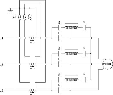
    Most large induction motors are started directly on line, but when very large motors are started that way, they cause a disturbance of voltage on the supply lines due to large starting current surges. To limit the starting current surge, large induction motors are started at reduced voltage and then have full supply voltage reconnected when they run up to near rotated speed.
    Two methods of reduced voltage starting are star delta starting and autotransformer stating. Contactors perform the switching action in the starter to connect and disconnect the power supply to the motor. If the current is above the rated current for the motor, the contactor will be tripped automatically to disconnect the motor from the supply.
    A three phase supply is given to the stator of the three phase induction motor, and this in turn produces a magnetic field which revolves in space around the stator. As if the magnetic poles are being rotated, the speed of the rotating magnetic field is given by
    N = 120 f /P
  • Starting Principle

    The high starting current will produce severe a voltage drop and will affect the operation of other equipment. It is not desirable to start large motors direct on line (giving full voltage to the stator). Normally with motors beyond 5 HP, starters are provided. For reduction in the starting current, a lower voltage is applied to the stator, especially for the squirrel cage induction motors. Full voltage is only applied when the motor picks up speed.
    Starting methods of Induction motor include:
    1. Direct –On– line (DOL) starters for less than 10 Kw motors.
    2. Star–Delta starters for large motors. The stator winding is initially connected in a star configuration and later on changed over to a Delta connection, when the motor reaches rated speed.
    3. Auto transformer.
  • 1. Direct On Line Starter

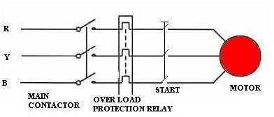
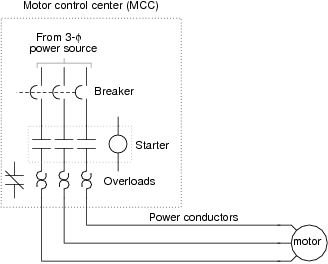
    DOL StarterDOL starter circuit diagram
    1. It is simple and cheap starter for a 3-phase induction motor.
    2. The contacts close against spring action.
    3. This method is normally limited to smaller cage induction motors, because starting current can be as high as eight times the full load current of the motor. Use of a double –cage rotor requires lower staring current( approximately four times) and use of quick acting A.V.R enables motors of 75 Kw and above to be started direct on line.
    4. An isolator is required to isolate the starter from the supply for maintenance.
    5. Protection must be provided for the motor. Some of the safety protections are over-current protection, under-voltage protection, short circuit protection, etc. Control circuit voltage is sometimes stepped down through an autotransformer.
  • 2. Star-Delta Starter

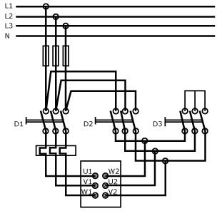
    Star-Delta Starter with circuit diagram
  • A three phase motor will give three times the power output when the stator windings are connected in delta than if connected in star, but will take 1/3 of the current from the supply when connected in star than when connected in delta. The starting torque developed in star is ½ that when starting in delta.
    1. A two-position switch (manual or automatic) is provided through a timing relay.
    2. Starting in star reduces the starting current.
    3. When the motor has accelerated up to speed and the current is reduced to its normal value, the starter is moved to run position with the windings now connected in delta.
    4. More complicated than the DOL starter, a motor with a star-delta starter may not produce sufficient torque to start against full load, so output is reduced in the start position. The motors are thus normally started under a light load condition.
    5. Switching causes a transient current which may have peak values in excess of those with DOL.
  • 3. Auto Transformer Motor Starting

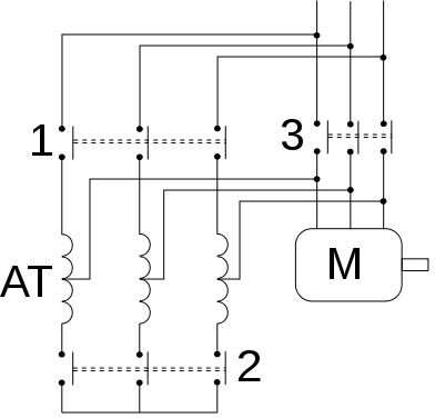
    1. Operated by a two position switch i.e. manually / automatically using a timer to change over from start to run position.
    2. In starting position supply is connected to stator windings through an auto-transformer which reduces applied voltage to 50, 60, and 70% of normal value depending on tapping used.
    3. Reduced voltage reduces current in motor windings with 50% tapping used motor current is halved and supply current will be half of the motor current. Thus starting current taken from supply will only be 25% of the taken by DOL starter.
    4. For an induction motor, torque T is developed by V2, thus on 50% tapping, torque at starting is only (0.5V)2 of the obtained by DOL starting. Hence 25% torque is produced.
    5. Starters used in lager industries, it is larger in size and expensive.
    6. Switching from start to run positions causing transient current, which can be greater in value than those obtained by DOL starting.
  • Auto Transformer StarterAuto Transformer Starter with Circuit Diagram
  • 4. Rotor Resistance Starter

    Roto-Resistance Starter
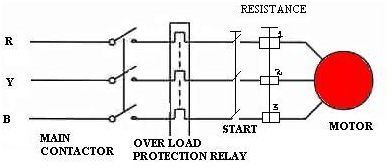
    1. This starter is used with a wound rotor induction motor. It uses an external resistance/phase in the rotor circuit so that rotor will develop a high value of torque.
    2. High torque is produced at low speeds, when the external resistance is at its higher value.
    3. At start, supply power is connected to stator through a three pole contactor and, at a same time, an external rotor resistance is added.
    4. The high resistance limits staring current and allows the motor to start safely against high load.
    5. Resistors are normally of the wire-wound type, connected through brushes and slip rings to each rotor phase. They are tapped with points brought out to fixed contactors.
    6. As the motor starts, the external rotor resistance is gradually cut out of circuit ; the handle or starter is turned and moves the three contacts simultaneously from one fixed contact to the next.
    7. The three moving contacts are interconnected to form a start point for the resistors.
    8. To ensure that the motor cannot be started until all rotor resistance is in circuit, an interlock is fitted which prevents the contactors from being closed until this condition is fulfilled.