Friday 14 December 2012

Automatic Train Operation(ATP)

Automatic Train Operation(ATP)

So far, we have only seen how ATP systems work on metros.  ATP is the safety system which ensures that trains remain a safe distance a part and have sufficient warning to allow them to stop without colliding with another train.  ATO (Automatic Train Operation) is the non-safety part of train operation related to station stops and starts.
The basic requirement of ATO is to tell the train approaching a station where to stop so that the complete train is in the platform.  This is assuming that the ATP has confirmed that the line is clear.  The sequence operates as shown below.

sig401.gif (3198 bytes) 

 The train approaches the station under clear signals so it can do a normal run in.  When it reaches the first beacon - originally a looped cable, now usually a fixed transponder - a station brake command is received by the train. The on board computer calculates the braking curve to enable it to stop at the correct point and, as the train runs in towards the platform, the curve is updated a number of times (it varies from system to system) to ensure accuracy.
London's Victoria Line, now 35 years old, has up to 13 "patches" checking the train speed as it brakes into a station. This high number of checks is needed because the on-board braking control gives only three fixed rates of deceleration.  Even then, stopping accuracy is ± 2 metres.    A detailed description of the Victoria Line's ATO system is here.    Modern systems require less wayside checking because of the dynamic and more accurate on-board braking curve calculations.  Now, modern installations can achieve ± 0.15 metres stopping accuracy - 14 times better.

Metro Station Stops

ATO works well when the line is clear and station run-ins and run-outs are unimpeded by the train ahead.  However, ATO has to be capable of adapting to congested conditions, so it has to be combined with ATP at stations when trains are closely following each other.  Metro operation at stations has always been a particular challenge and, long before ATO appeared in the late 1960s, systems were developed to minimise the impact when a train delayed too long at a station.
sig402.gif (3680 bytes)
 To provide a frequent train service on a metro, dwell times at stations must be kept to a minimum.  In spite of the best endeavours of staff, trains sometimes overstay their time at stations, so signalling was been developed to reduce the impact on following trains.  To see how this works, we begin with an example (left) of a conventionally signalled station with a starting Signal A1 (green) and a home Signal A2 (red) protecting a train (Train 1) standing in the station.  We can assume mechanical ATP (trainstops) is provided so the overlap of Signal A2 is a full speed braking distance in advance of the platform.
As Train 2 approaches, it slows when the driver sees the home Signal A2 at danger.  Even if Train 1 then starts and begins to leave the station, Signal A2 will remain at danger until Train 1 has cleared the overlap of Signal A1.  Train 2 will have to stop at A2 but will then restart almost immediately when Signal A2 clears.  This causes a delay to Train 2 and it requires more energy to restart the train.  A way was found to allow the second train to keep moving.  It is called multi-home signalling.

Multi Home Signalling - Approach

sig403.gif (6982 bytes)
Where multi-home signalling is installed at a station (left), it involves the provision of more but shorter blocks, each with its own signal.  The original home signal in our example has become Signal A2A and, while Train 1 is in the platform, it will remain at danger.  However, Block A2 is broken up into three smaller sub-blocks, A2A, A2B and A2C, each with its own signal.  They will also be at danger while Train 1 is in the platform.  Train 2 is approaching and beginning to brake so as to stop at Signal A2A.
When Train 1 begins to leave the station, it will clear sub-block A2A first and signal A2A will then show green.  Train 2 will have reduced speed somewhat but can now begin its run in towards the platform.

Multi Home Signalling - Run In

sig404.gif (6926 bytes)
 At this next stage in the sequence, we can see (left) that Train 1 has now cleared two sub-blocks, A2A and A2B, so two of the multi-home signals are now clear.  Note that the starting signal is now red as the train has entered the next block A1.  Train 2 is running towards the station at a reduced speed but it has not had to stop.
When Train 1 clears the overlap of signal A1, the whole of block A2 is clear and signal A2C clears to allow Train 2 an unobstructed run into the platform.

ATO/ATP Multi Home Signalling

sig405.gif (7513 bytes)
 Fixed block metro systems use multi-home signalling with ATO and ATP.  A series of sub-blocks are provided in the platform area.  These impose reduced speed braking curves on the incoming train and allow it to run towards the platform as the preceding train departs, whilst keeping a safe braking distance between them.  Each curve represents a sub-block. Enforcement is carried out by the ATP system monitoring the train speed.  The station stop beacons still give the train the data for the braking curve for the station stop but the train will recalculate the curve to compensate for the lower speed imposed by the ATP system.

ATO Docking and Starting

sig406.gif (3173 bytes)
 In addition to providing an automatic station stop, ATO will allow "docking" for door operation and restarting from a station.  If a "driver", more often called a "train operator" nowadays, is provided, he may be given the job of opening and closing the train doors at a station and restarting the train when all doors are proved closed.  Some systems are designed to prevent doors being opened until the train is "docked" in the right place.  Some systems even take door operation away from the operator and give it to the ATO system so additional equipment is provided as shown left.
When the train has stopped, it verifies that its brakes are applied and checks that it has stopped within the door enabling loops.  These loops verify the position of the train relative to the platform and which side the doors should open.  Once all this is complete, the ATO will open the doors.  After a set time, predetermined or varied by the control centre as required, the ATO will close the doors and automatically restart the train if the door closed proving circuit is complete.  Some systems have platform screen doors as well.  ATO will also provide a signal for these to open once it has completed the on-board checking procedure.  Although described here as an ATO function, door enabling at stations is often incorporated as part of the ATP equipment because it is regarded as a "vital" system and requires the same safety validation processes as ATP.
Once door operation is completed, ATO will then accelerate the train to its cruising speed, allow it to coast to the next station brake command beacon and then brake into the next station, assuming no intervention by the ATP system.

Sidharthan G
electricalmiracles.

Tags:Automatic train operation,train operation,metro train control,chennai metro,chennai metro rail,metro rail. 


Sunday 9 December 2012

PICsim - PIC microcontroller simulator

PICsim - PIC microcontroller simulator 

Download
Sidharthan G
electricalmiracles. 
Tags:PICsim,PIC microcontroller simulator,download free.

Sunday 4 November 2012

LED Blinking PIC16F877A

void main()
        {
        TRISB = 0 ;     // set PORTB as OUTPUT         for(;;)         // forever
                {
                PORTB = 0xff ;          // turn all LEDs ON
                Delay_ms(500) ;         // wait 500 ms
                PORTB = 0 ;             // turn all LEDs OFF
                Delay_ms(500) ;         // wait 500 ms
                }
        }

Sidharthan G
electricalmiracles.
 

Friday 2 November 2012

Components Of Electrical Substation


A:Primary power lines' side B:Secondary power lines' side
1.Primary power lines 2.Ground wire 3.Overhead lines 4.Transformer for measurement of electric voltage 5.Disconnect switch 6.Circuit breaker 7.Current transformer 8.Lightning arrester 9.Main transformer 10.Control building 11.Security fence 12.Secondary power lines
Sidharthan G
electricalmiracles. File:Electrical substation model (side-view).PNG

LVDT Displacement Transducer

An LVDT Displacement Transducer comprises 3 coils; a primary and two secondaries.

The transfer of current between the primary and the secondaries of the LVDT displacement transducer is controlled by the position of a magnetic core called an armature.


The two transducer secondaries are connected in opposition.

At the centre of the position measurement stroke, the two secondary voltages of the displacement transducer are equal but because they are connected in opposition the resulting output from the sensor is zero.

As the LVDTs armature moves away from centre, the result is an increase in one of the position sensor secondaries and a decrease in the other. This results in an output from the measurement sensor.

With LVDTs, the phase of the output (compared with the excitation phase) enables the electronics to know which half of the coil the armature is in.

The strength of the LVDT sensor's principle is that there is no electrical contact across the transducer position sensing element which for the user of the sensor means clean data, infinite resolution and a very long life.

Our range of signal conditioning electronics for LVDTs handles all of the above so that you get an output of voltage, current or serial data proportional to the measurement position of the displacement transducer.

Sidharthan G
electricalmiracles.

Thursday 1 November 2012

Cell Phone Detector

http://electroschematics.com/wp-content/uploads/2009/01/cellphone-detector.jpg

Earth Fault Indicator circuit

Earth Fault Indicator circuit

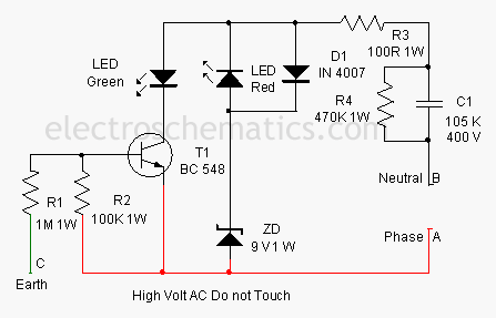
This circuit indicates the integrity of wiring connections. It shows all the mains connections – Phase, Neutral and Earth connections – are intact or not. The circuit is too small and can be housed in a three pin plug case.

Earth Fault Indication Circuit Diagram


The circuit is directly connected to mains to monitor the status of the connections. Earth connection is a must in domestic wiring to bleed current to the earth if the metal body of a device is accidentally touched with the phase line. This circuit indicates
1. Red and Green LEDs ON Phase, Neutral and Earth OK
2. Red and Green LEDs OFF Phase or Neutral Break / Power failure
3. Red LED ON Phase and Neutral OK
3. Green LED OFF Earth line break
The circuit gets power supply through C1 and R3. AC Capacitor C1 reduces the high volt AC to a safer level through capacitive rectance. Resistor R3 limits the inrush current and R4 gives discharge path for the stored current in C1 when the circuit is unplugged. Zener diode ZD regulates the voltage to a safer level to protect T1 when it is off. Voltage across ZD will be a square wave by the working of C1 and the voltage level depends on the breakdown value of zener (9 volts). When a potential of 230 volt is present between the phase and neutral lines, T1 turns on during the negative half cycle of AC and Green LED lights indicating that Earth connection is intact. This is because the base of T1 will be biased by the potential difference between the phase line and earth. If the earth connection is not intact, T1 will not get base bias and it remains off. Red LED lights during the positive half cycle of AC due to the potential difference between the phase and neutral lines.
Enclose the circuit in a 3 pin plug and connect points A, B and C to the phase, neutral and earth pins respectively. Plug it into the 3 pin socket to test the wiring.

Transformer Less Power Supply Circuit Diagram

TransformerLess Power Supply 12V 100mA

This is a transformerless power supply for low current applications. C1 is the X rated AC capacitor that reduces high volt AC. D1-D4 rectifies AC to DC and C2 removes ripples. R1 is the bleeder to remove stored current in AC when power is off. R2 limits inrush current. A Zener can be used in the output to get regulated DC.


Tags: transformerless power supply project,transformer less,power transformer less,transformer less,no transformer

Tuesday 30 October 2012

PIC C An introduction to programming the Microchip PIC in C

PIC C An introduction to programming the Microchip PIC in C


PIC C An introduction to programming the Microchip PIC in C
Author Nigel Gardner | Year 1998 | ISBN : 1899013067 | 162 pages | Pdf | 7 mb

1. C Fundamentals
2. Variables
3. Functions
4. C Operators
5. C Program Control Statements
6. Arrays and Strings
7. Pointers
8. Structures and Unions
9. PIC Specific C
http://rapidshare.com/files/333776996/PICC.pdf
Sidharthan G
electricalmiracles. 

PIC Microcontrollers - Programming in C

  • Title :PIC Microcontrollers - Programming in C
  • Author(s): Milan Verle
  • Publisher: mikroElektronika; 1st edition (2009)
  • Paperback 336 pages
  • Language: English
  • ISBN-10: N/A
  • ISBN-13: 978-8684417178
  • Share This:                    
Book Description
This book is the perfect for entry into this world for engineers who have not worked with PICs, new professionals, students, and hobbyists. As MCUs become more complex C is the most popular language due to its ability to process advanced processes and multitasking. RTOSs, that is a need to know for engineers, is also discussed as more advanced MCUs require timing and organization of programming and implementation of multitasking.
What are microcontrollers, anyway? Electronics built in one single chip capable of controlling a small submarine, a crane or an elevator… It’s up to you to decide what you want them to do and dump a program containing appropriate instructions into the chip.
PIC Microcontrollers are present in almost every new electronic application that is released from garage door openers to the iPhone. With the proliferation of this product more and more engineers and engineers-to-be (students) need to understand how to design, develop, and build with them. Martin Bates, best-selling author, has provided a step-by-step guide to programming these microcontrollers (MCUs) with the C programming language.
On the other hand, the microcontroller is designed to be all of that in one. No other specialized external components are needed for its application because all necessary circuits which otherwise belong to peripherals are already built in it. It saves time and space needed to design a device.
About the Authors
  • N/A
Reviews and Rating:
  • N/A
Related Books and Categories: Read and Download Links:

Sunday 28 October 2012

Automatic Water Level Controller

 
Program:-
// LCD module connections

sbit LCD_RS at RB2_bit;
sbit LCD_EN at RB3_bit;
sbit LCD_D4 at RB4_bit;
sbit LCD_D5 at RB5_bit;
sbit LCD_D6 at RB6_bit;
sbit LCD_D7 at RB7_bit;

sbit LCD_RS_Direction at TRISB2_bit;
sbit LCD_EN_Direction at TRISB3_bit;
sbit LCD_D4_Direction at TRISB4_bit;
sbit LCD_D5_Direction at TRISB5_bit;
sbit LCD_D6_Direction at TRISB6_bit;
sbit LCD_D7_Direction at TRISB7_bit;
// End LCD module connections

char txt1[] = "Project";
char txt2[] = "Developed By....";
char txt3[] = "Ashno and Akhil";
char txt4[] = "---------------";

char mtr1[] = "Motor ";
char mtr2[] = "OFF";
char mtr3[] = "ON";

char wtr1[] = "Level: ";
char wtr2[] = "Very Low";
char wtr3[] = "Low";
char wtr4[] = "Medium";
char wtr5[] = "High";
char wtr6[] = "Full";


void main()
{

  int i = 0;
  int c = 16;
  int b = 0;
  CMCON = 0x07;
  ADCON1 = 0x06;
  TRISA = 0x0F;          // set direction to be input
  PORTA = 0x00;
  PORTD = 0x00;
  PORTC = 0x00;
  TRISB = 0x00;          //  set direction to be output
  TRISC = 0x00;          // set direction to be output
  TRISD = 0x80;          // set direction to be output

  PORTD.F2 = 1;
  PORTD.F7 = 1;

  Lcd_Init();                        // Initialize LCD
  Lcd_Cmd(_LCD_CLEAR);               // Clear display
  Lcd_Cmd(_LCD_CURSOR_OFF);          // Cursor off
  Lcd_Out(1,1,txt1);                 // Write text in first row
  Lcd_Out(2,1,txt2);                 // Write text in second row
  Delay_ms(500);
  Lcd_Cmd(_LCD_CLEAR);               // Clear display
  Lcd_Out(1,1,txt3);                 // Write text in first row
  Lcd_Out(2,1,txt4);                 // Write text in second row
  Delay_ms(500);

// Moving text
for(i=0; i<15; i++)
{ // Move text to the right 16 times
  Lcd_Cmd(_LCD_SHIFT_RIGHT);
  Delay_ms(125);
}
i=0;

do
{
   Lcd_Cmd(_LCD_CLEAR);
   Lcd_Out(1,1,wtr1);
   Lcd_Out(2,1,mtr1);
   if(c>0)
   {
      PORTD.F2 = 1;
      c--;
   }
   else
      PORTD.F2 = 0;
    
   if(b>0)
   {
       PORTD.F0 = 1;
       Delay_ms(125);
       PORTD.F0 = 0;
       b--;
   }


   if(PORTD.F7 == 0)
     c = 16;
   
   if(PORTA == 0x0F)
   {
       PORTD.F1 = 1;
       Lcd_Out(1,8,wtr2);
       Lcd_Out(2,7,mtr3);
       PORTC = 1;
       if(i == 0)
       {
          c = 16;
          b=3;
       }
       i=1;
   }
   else if(PORTA == 0x0E)
   {
       Lcd_Out(1,8,wtr3);
       if(i == 1)
          Lcd_Out(2,7,mtr3);
       else
          Lcd_Out(2,7,mtr2);
       PORTC = 3;
   }
   else if(PORTA == 0x0C)
   {
       Lcd_Out(1,8,wtr4);
       if(i == 1)
          Lcd_Out(2,7,mtr3);
       else
          Lcd_Out(2,7,mtr2);
       PORTC = 7;
   }
   else if(PORTA == 0x08)
   {
       Lcd_Out(1,8,wtr5);
       if(i == 1)
          Lcd_Out(2,7,mtr3);
       else
          Lcd_Out(2,7,mtr2);
          PORTC = 15;
   }

   else if(PORTA == 0x00)
   {
       Lcd_Out(1,8,wtr6);
       Lcd_Out(2,7,mtr2);
       PORTD.F1 = 0;
       if(i == 1)
       {
         c = 16;
         b = 3;
       }
       i=0;
       PORTC = 31;
   }
   else
       PORTA = 0x0F;
   Delay_ms(125);


}while(1);            // Endless loop
}